
The plan for the vent system.
This is how I envisaged the working of the vent, fan and shutter.
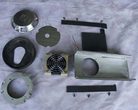
The parts ready to assemble.
On the far left is an extra vent kit - from the bottom to the top:
- the external aluminum plate with the centre cut out to a 3" diameter hole. It will screw through van wall onto the plastic circle inside (not visible) and have a flexible hose clamped to it,
- the rubber gasket, yet to have the hole cut out to 3". Because the original vent was off centre, part of the rubber had to be filled in to match up with the plastic circle,
- the stainless steel baffle plate from the original vent, which was used to separate the fresh intake air from the burnt exhaust. It will be used just as a baffle against rainwater. Also to be fitted will be a bug screen,
- the external stainless steel shield.
Below that is a plastic retainer strip for the shutter, and above is the sliding shutter and another retainer strip. On the final version, the tab was removed from the shutter.
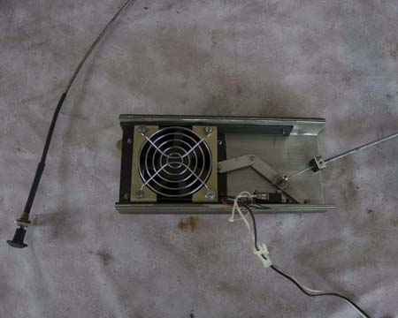
The shutter closed.
The shutter opens and closes by a choke cable. The lever system is needed to move the shutter 3" for only a 1 1/2" movement of the choke knob.
The microswitch on the bottom side closes when the shutter is fully opened, supplying 12V to the fan.
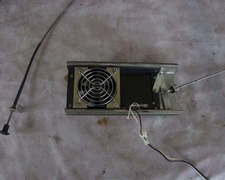
The shutter open.
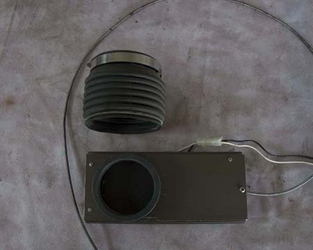
The flexible connection.
The black flexible hose is actually the air intake from a Ford car cut down to 3 1/2" length to fit between the outer metal and the inner panel. The diameter was perfect at 3 5/8".
The worm clamp holds it permanently to the plastic ring on the outer vent, the spring holds it to the plastic ring on the inner unit and can be slipped off if the fan needs servicing, without disturbing the outer parts.
Unfortunately the fridge will have to be removed first!
The unit is only 2" thick, but only 1" protrudes into the space behind the fridge so there is plenty of room.
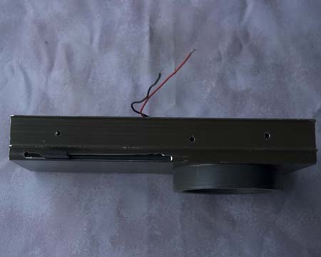
Side view.
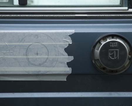
Marking the exterior.
The next frightening step was marking out and cutting a hole in the side of the van. A jigsaw with metal cutting blade worked well. I wanted the two vents to be perfectly in line, and spaced 10" apart. They could have been physically closer, but I didn't want air entering and exiting each one to affect the other.
The hole in the outside metal is 3" diameter.
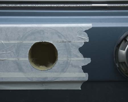
The rough cut.
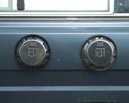
The final result.
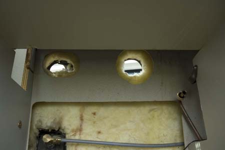
The interior hole.
Cutting the hole through the interior panel behind the fridge was more difficult. It had to be done by hand with a cut down hacksaw blade!
Because of the grill behind the stove, it had to be centred 1" below the outer hole.
To allow for the flexible connection, this hole was cut to 4" diameter.
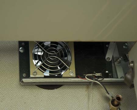
The unit installed.
The unit was mounted right up against the grill behind the stove, and held to the interior panel with 3 screws.
The choke cable is mounted below the shelf in the right hand cupboard

The unit mounted, and shutter control.
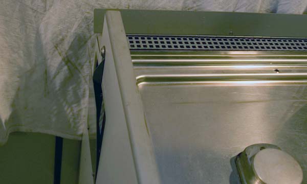
Interior flaps open.
The final step was to make a narrow hinged flap to fit behind the stove which can be opened to allow hot air to rise by natural convection into the van from behind the fridge and a flap in place of the grill on the left side of the stove. This can be locked closed, or wedged open by the small tab. With these flaps open, the heat from the fridge vents naturally into the van, as it did originally, shown on the left, - or
closed when the heat is to be vented to the outside by the fan (hopefully nicer on hot evenings), shown on the right.
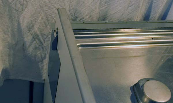
Interior flaps closed.
I don't know what the accompanying graph tells, but it was an interesting 'science fair project'! I will try to do another one with more controls later.
