Westfalia

Auxilliary Water Heater

The installation of the engine powered shower water heater was a great success. The water heated within half an hour of driving and would stay hot well into the evening. However, we usually found that it was not warm enough after an overnight stop.

So, the plan is to use the waste heat from the Dometic fridge overnight to keep the water in the tank warm enough to use in the morning. In its job of heating the ammonia solution to cool the inside of the fridge, the Dometic puts at least 50oC of heat out the flue pipe - wasted heat!

Click on the image to see it full size.

Auxilliary Water Heater - Part 1

Not completely successful, but proved the theory.

The Plan for the Heater
A length of 1/4" copper pipe would be bent to fit against the flue pipe, underneath the fibreglass insulation.

Cooler water from the bottom of the tank would enter the tubing at the bottom of the serpentine, be heated by the flue pipe and return to the top of the tank, heated. If the levels between the flue pipe and the tank are correct, this will take place by thermosiphon effect. In my '88 Westfalia, the sink water comes from an outlet near the bottom of the tank. However, I discovered that in an '89, the in-tank pump pumps water out the top of the tank. If things do not line up, a small circulating pump will be installed.
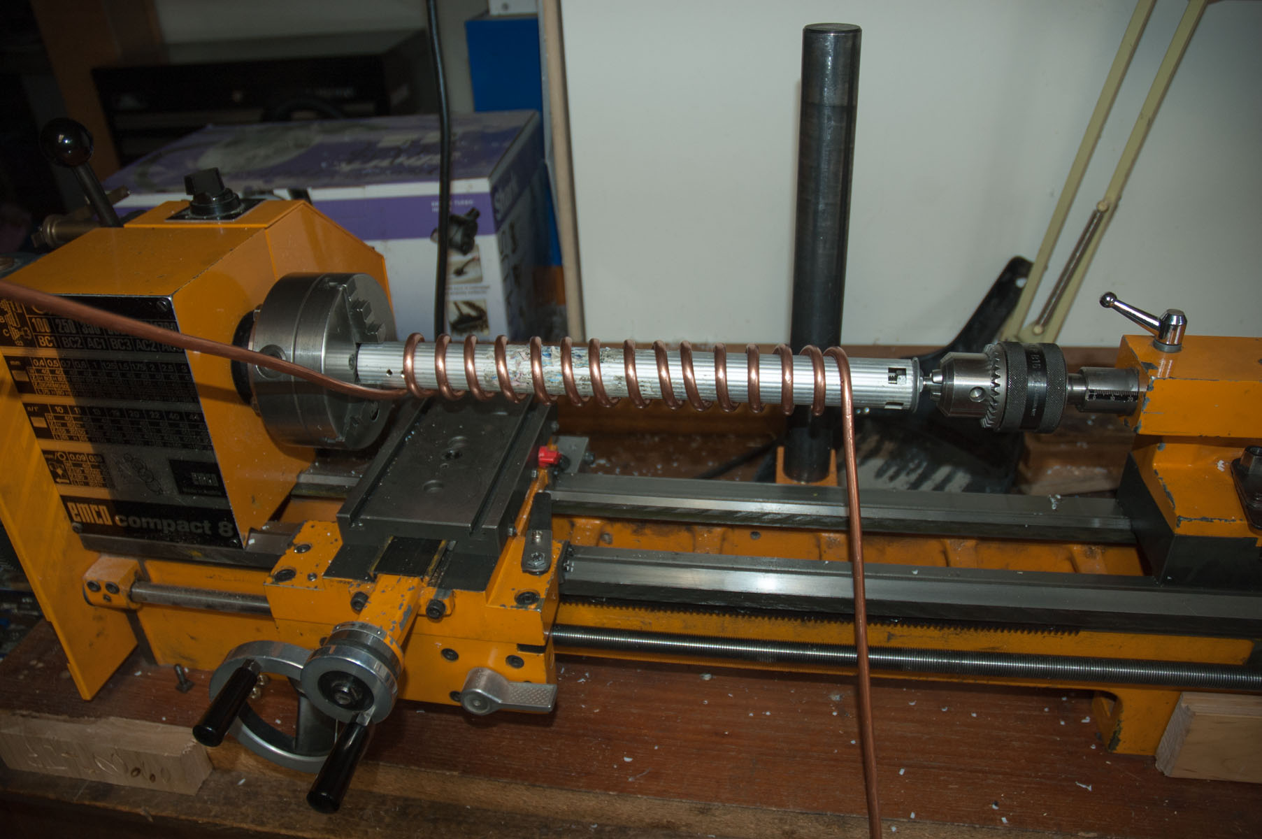

Bending the Tube

A bending jig was made from scrap maple hardwood flooring. As the first few kinks were bent, the formers were unscrewed and moved further along to the right.

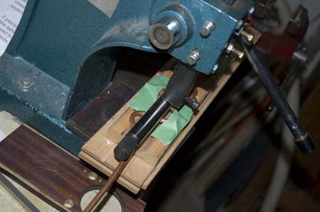
Curving the Serpentine

With an armature press, a 3/4" steel bar, the same diameter as the flue pipe, pressed the serpentine of copper tubing into another jig (also of scrap maple flooring) with a 1 1/4" diameter concave shape in it.


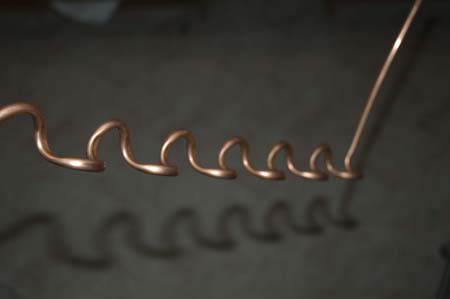
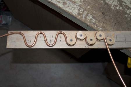
The Curved Serpentine

All bent, curved and ready to install. The result uses nearly 42" of tubing within 14" of length. The nearly semi-circular shape was used because the tubing could not be wrapped completely around the flue pipe. The 12V and 120V heater elements, as well as the ammonia boiling tube are bonded to the flue pipe for the lower 1/4 of its length. As well, installing it would mean removing the brass ferrule and flexible flue.


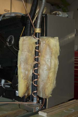
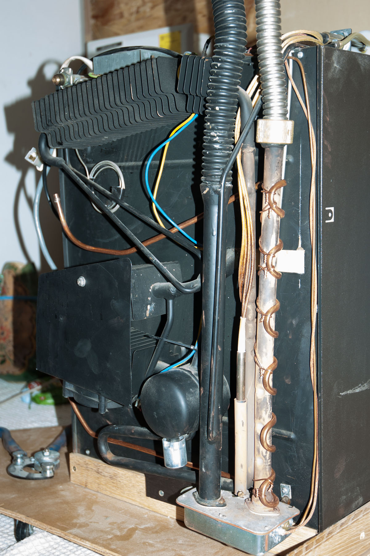
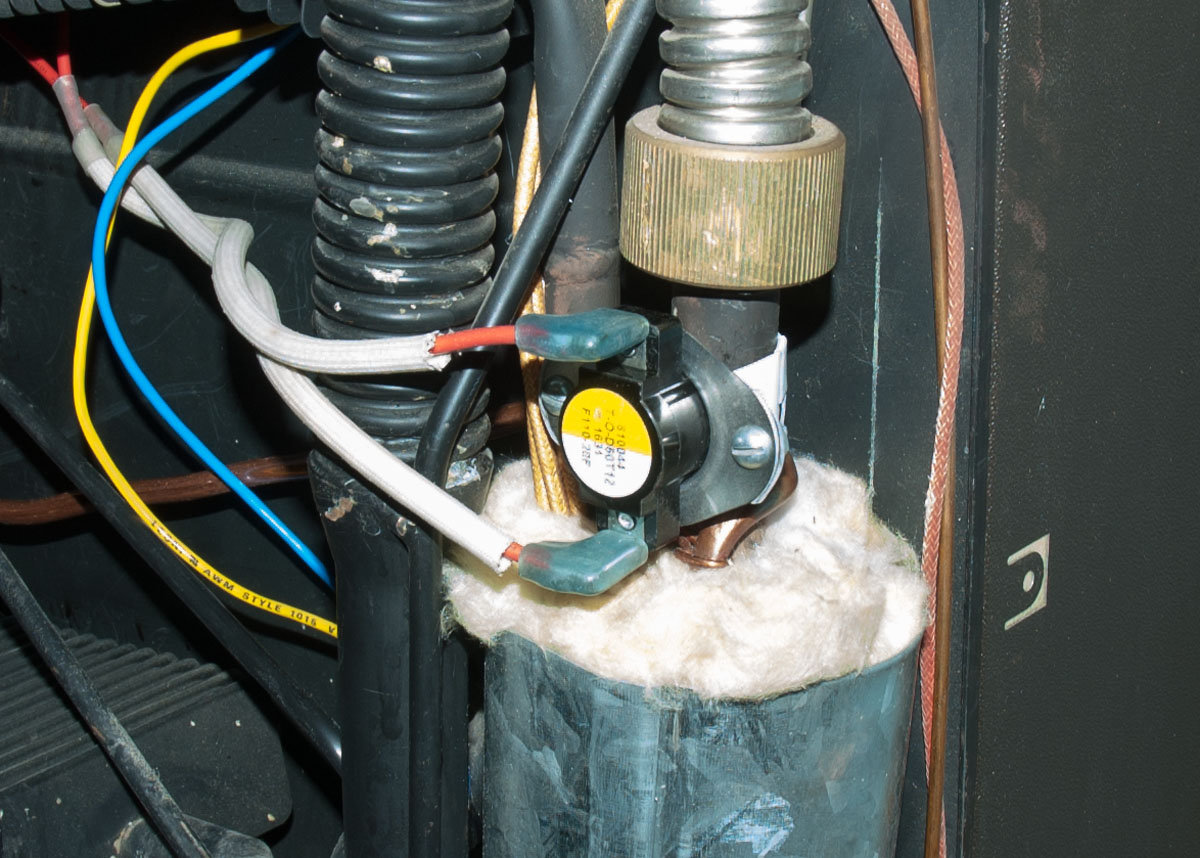
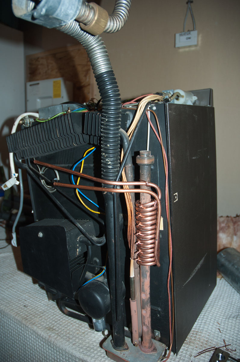
Fitted to the Dometic
The steel shroud has been unclipped and slipped off the flue pipe and the fibreglass insulation peeled back exposing the flue pipe, boiler tube and heater elements.

The copper tube serpentine has been fitted to the flue, tied with wire so it is in direct contact with the flue pipe.

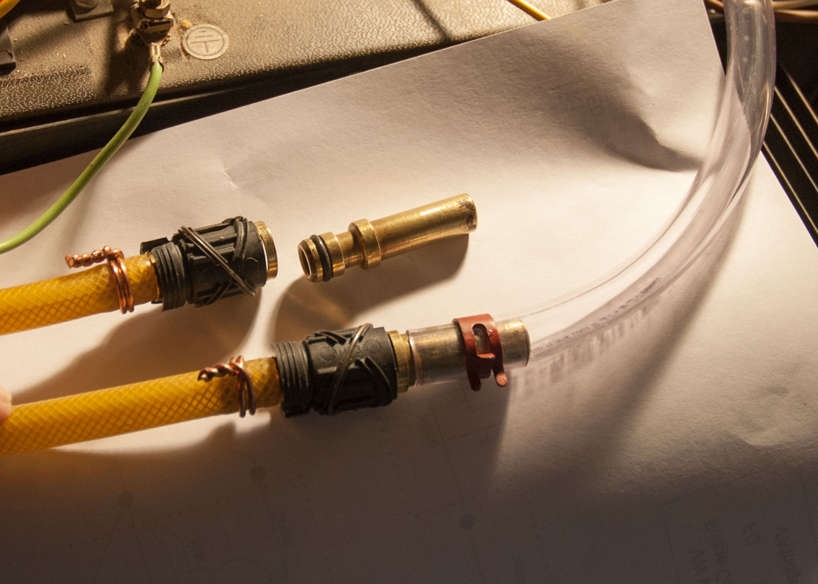
At the moment there is 6' of 3/8" plastic hose on the inlet and another 6' on the return side of the heating tube. This length is greater than the distance between the fridge and the water tank when properly installed in the Westfalia.
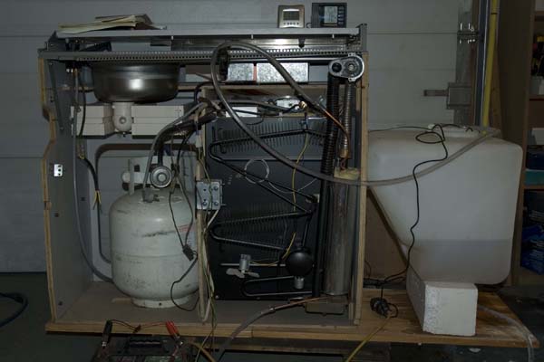
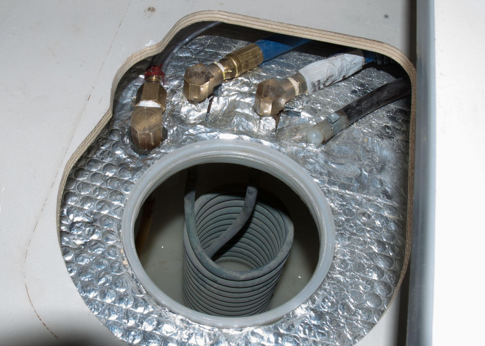
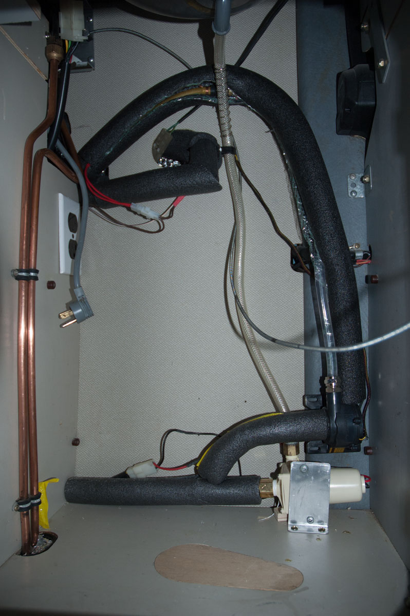
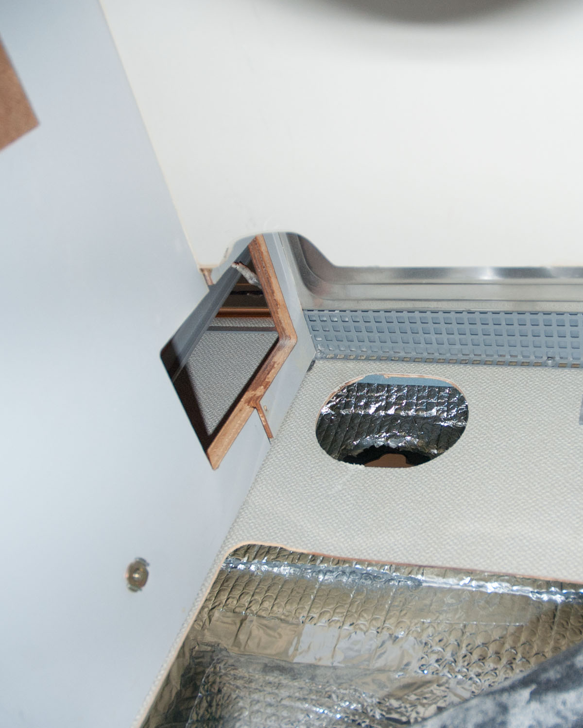

The Test Setup

With a fridge, propane bottle, battery and water tank (from an '89), testing takes place.

In the first test a 1 liter water tank was used. By thermosiphon action, the temperature of the water was raised from 13oC to 53oC in 5 hours. Meanwhile the fridge was chilling the beer!

However when the experiment was enlarged to using the Westfalia tank, thermosiphon effect would not work! The storage was at the same height as the heater tube, so water would not circulate.

At this time neither the tank nor the plastic tubing is insulated, so probably loses a lot of heat in the transferring process.
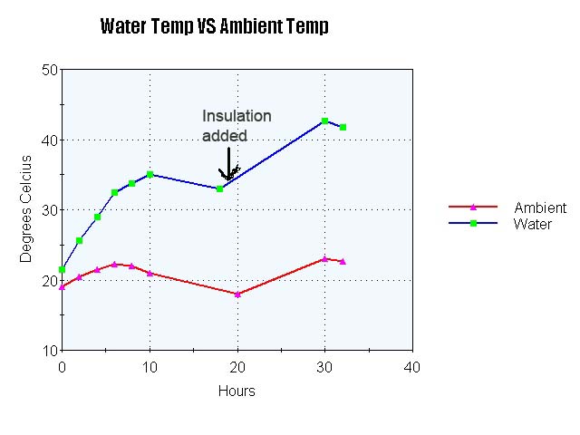

Graph of Results
Because thermosiphon effect would not work, a small submersible pump was installed in the tank, which was was filled about 1/3 full.

The water temperature rose from 19 to 35oC in 11 hours, despite neither the tank nor the tubing being insulated.

Part way through the experiment the tank was insulated with a blanket, and the temperature rose to 42.6oC - which should be perfect for a shower.

For a final test, the tank was filled to the FULL indicator (about 39 litres of water) and left for 12 hours. It maintained around 40oC.

Since the aim of the project is to simply maintain the temperature of the stored water at around 42oC over night, after it has been heated by the vehicle's engine, this looks promising.

Auxilliary Water Heater - Part 2

An improvement, but still not satisfactory.


The next difficulty in implementing this mod was to allow the fridge to be removed and replaced easily. Since the copper serpentine tubing will be built into the fridge heating flue, some form of quick connect or unions for the water tubing is needed.


The Revised Plan, with more detail
This revised plan allows for a circulating pump mounted under the sink cabinet,
quick connect fittings at the fridge to allow it to be removed easily
and some simple electrical circuitry.

The water will flow from the bottom of the tank towards the ShurFlo pump under the sink. When the circulating pump is running, it will circulate water through the serpentine and return to the top of the hot water storage tank.


The Copper Serpentine fastened with copper wire.
The serpentine is bound as tightly as possible to the fridge flue pipe with copper wire. This will be covered with the original fibreglass insulation and metal sleeve.

Although it looks inconvenient to run the copper tube across the back of the fridge to join the flexible rubber hose and quick connect unions, it will allow these fittings to be reached in the cupboard under the sink.

Unfortunately the serpentine idea did not work successfully!

Keep reading.


The Quick Connect water line connectors
These connectors are recycled from a kitchen sink. The original very stiff high pressure hose was removed by grinding off the brass ferrule. One end fits into the 1/4" ID rubber hose and the other piece fits into the 3/8" ID plastic hose and is clamped tightly. As the system is not under pressure the clamping is not as critical as in a kitchen sink setup.

By squeezing the black collars, the brass fitting can be pulled out. No tools needed. These connectors do not block water exiting, so the tank may have to be drained before removing the fridge.


The Simple Wiring Diagram
The wiring for the mod is simple. Continuous +12V will be taken from the auxilliary circuit. A snap disc thermostat is wired in series with an adjustable thermostat to the circulating pump.

The snap disc thermostat is mounted tightly to the top end of the Dometic fridge flue pipe. It is in a normally open state and closes at around 43oC*C (110*F). This will allow the system to circulate water only when the heat in the flue pipe is high enough to be practical.

The adjustable thermostat probe is mounted at the bottom of the hot water tank. It is in a normally closed state and can be set to open when the water in the tank reaches a comfortable temperature.

The circulating pump is a Thermaltake brand P500 pump designed for liquid cooling systems in gaming computers. It runs silently, takes 12V DC at 600 mA, and claims to be able to pump 500 liters/min.


Plumbing into the Tank

The water returns to the hot water tank through plastic 3/8" ID hose and brass fittings through a hole drilled into the top of the water tank. Rubber gaskets seal the fitting inside and out. The plastic hose runs through the cabinet wall and behind the fridge to the under-sink cabinet. It is sheathed in a foam insulation tubing to prevent kinks and retain heat.

Left fitting: hot water return from Dometic fridge.
Inside the tank a piece of flexible 1/4" ID tubing simply drops down. The idea is to have the water return at or near the water level in the tank to prevent water splashing noises all night.

Blue hose: coolant return to engine cooling system.
White hose: hot water from engine cooling system into heat exchange coil.
These and the copper coil seen inside the tank are part of the previous water heating mod, using engine coolant.

Right, black hose: tank vent to filler port


Snap Disc Thermostat

A snap disc thermostat is fastened to the Dometic flue pipe, near the top. This will prevent the circulating pump from running until the heat is at a sufficient level. It will be covered with fiberglass insulation.

A test of temperatures (in oC) at the fridge flue shows:
  At top At bottom
Propane 152, 150, 148 275, 265, 275
110 Volt 78 80
110 + gas 115, 140, 147 250, 255, 275
12V DC 52, 54, 55 70, 73, 76

This indicates that the pump will circulate when the fridge is running on propane, 120V AC or 12V DC as the flue temperature should reach 43oC (110*F).

Also it is interesting to note that the flue is hotter at the bottom than the top.


Everything Under the Kitchen Sink

The pump, plumbing, connectors and wiring are all fitted in the cabinet under the sink.

The cable protruding out of the cabinet is a mechanical cable to operate the fan switch and ventilator shutter to the outside of the van. (A previous mod)

The white pump is a ShurFlo replacement for the original Westfalia unit, to feed the shower hose which runs up through the bottom of the sink bowl.

The thin black wire connects the circulating pump to the snap disc thermostat, adjustable thermostat and 12V power.

The black pump is the water circulating pump.

The looped hose sends warmed water from the serpentine back to the storage tank.

The right hand hose pumps the water into the serpentine.

The lower pump and tubing will be covered by a protective shelf.


Heat Test Graph 2

With the fridge installed in the van, all plumbed, insulated and wired in, a test was done to determine temperatures.

By hour 13, heating and circulation heated the water in the tank to a consistent 30.9oC.

Around hour 21 I realized that the fridge was not as cold as it should be, so started to take temperature readings inside the fridge.

Between hour 25 and hour 40 I stopped the circulating pump and the fridge temperature dropped considerably, to -6.5oC, 17.5 degrees below ambient - almost normal.
Reconnecting the pump again caused the fridge temperature to rise.

From this it would appear that the water circulating through the serpentine around the flue pipe is drawing too much heat away from the ammonia boiling tube, causing very reduced efficiency of the Dometic fridge.

The next step will be to reconfigure the serpentine into a coil around the flue pipe - only at the top 1/3 of its height - well away from the ammonia boiling tube at the bottom.


Blank

Interpreting the graph above shows:

Water temperature rise from 8.4 to 26.4 over 14 hours gives an average of 1.28*/hr. Maximum heat reached 30.9oC.

Water temperature drop from the maximum of 30.9 down to 19.6 over 14 hours gives an average loss of .81*/hr.

Meanwhile while the pump was running, the fridge temperature did not go below +6.4oC!

Fridge cooling from 6.4 down to -6.5 over 13 hours gives an average of 1*/hr while the pump is NOT running.

Fridge temperature loss (once turned off) from -6.5 up to 4.0 over 10.5 hours gives an average rise of 2.1*/hr.


Winding the New Coil

The soft copper tube is wrapped by hand around aluminum tubes of diminishing diameters until it reached the correct size. The lathe is just used as a solid working platform.

About 72" of tube makes the coil, with about 12" leads at each end.

I felt that not enough 1/4" pipe could be contained in a sepentine due to the diameter of the bends, so a coil was made instead.


New Heat Coil Around the Flue Pipe

The second version of the Dometic flue pipe heat exchanger.


The new coil of 1/4" soft copper tube was made to fit over the upper part of the fridge flue pipe.

Unfortunately the inner diameter of the coil had to be 1 1/4" (32mm) to allow it to slide over the threaded connecter for the flue flex pipe. This means the copper coil does not touch all around the flue pipe as it is only 3/4" (20mm) diameter. Therefore it was wired tightly to one side of the flue pipe.


Heat Coil Insulated

The original insulation and metal shield was replaced over the flue pipe and ammonia boiler tube and the new copper coil.

Extra insulation was added above to cover the snap disc thermostat and copper tubing. It is fastened with heat resistant aluminum tape.


Modifying Under the Stove

Having removed and installed the fridge so many times, I looked for the reason it was so difficult.

Looking upward inside the fridge cavity, the reason is the lack of clearance between the shelf below the stove and the flue flex pipe while the fridge is being pulled out or pushed in.

The solution was to cut a small notch out of that shelf. It should have been a little longer to the right side, but even as is installation is much easier.

The oval hole is where the flue flex pipes pipes exit the cabinetry and van wall.


Heat Test Graph 3

With the new coil installed a third set of tests resulted in this graph.

After 32 hours the water temperature reached only 28oC.

Meanwhile the fridge reached a low of only -4.5 degrees. It can do better!

When the circulating pump was turned off the fridge dropped to -7.1 degrees, or 18 degrees below ambient.


Heat Test Graph 4

A fourth set of tests resulted in this graph.

At hour 38 the van engine was started with hot coolant flowing through the heat exchanger coil in the water tank. By hour 39 1/2 the water temperature had risen from 19.9 to 39.9oC.

At that point the circulation pump was started, circulating hot tank water through the coil on the Dometic fridge flue pipe. The temperature dropped from the high of 37.9 down to 33oC by hour 43.

During this time the fridge temperature rose from -8.2 to -7oC, indicating that the copper coil is still drawing heat from the ammonia boiling tube, lessening the efficiency of the fridge.


Heat Test Graph 5

As a continuation of the above graph, the water temperature dropped from 33 to 30oC over about 7 hours and then remained steady for the next 12 hours.

This shows how the Dometic fridge heater coil helped maintain the heat over a long period.

However the fridge rose from -6 to -4oC giving a differential of 16 degrees below ambient. It should be closer to 19 or 20 degrees.

The fridge did not suffer such a large loss of efficiency as in the earlier tests but I feel another modification to the copper coil could improve both the water heating and fridge cooling effect.

Auxilliary Water Heater - Part 3

The final step was to place a newer version of the copper heat coil, with tighter coils, around the corrugated upper flue flex pipe.


The new tighter coil in place

This coil has about 11 wraps and fits tightly against the corrugated upper flexible flue pipe, just above the brass ferrule. It is insulated with fiberglass and aluminum tape.

Further fiberglass insulation was added around the copper tube up to the foam rubber insulation.


Heat Test Graph 6

This 48 hour test, used only the Dometic fridge to heat the water in the storage tank. Water temperature reached 23.5oC, almost 6 degrees above ambient, not quite as hot as previous versions.

This version of heat coil did not rob the ammonia boiler tube of its heat, so the fridge stayed as cool as normal - about 18-20 degrees Celsius below ambient.


Heat Test Graph 7

This really is the last graph! As a continuation of the above graph, the engine was started and the van taken for a drive. The water heat reached about 37oC, the water circulation pump was turned off.

When the water temperature decreased to about 33oC the pump was turned on again.

This kept the water at just under 33 degrees for 9 hours (until hour 12) when eveything was shut off. The fridge temperature did rise to 1oC above zero, but the ambient was now over 20 degrees Celsius, so a differential of 18 to 19 degrees was maintained.

So it would seem that the Dometic water heater can maintain a full tank of water at an acceptable 33 degrees Celsius for 9 hours, while the fridge did not suffer a loss of efficiency as in the earlier tests.

A 10 day road trip in June tested the latest setup. It did work as tested. A slightly higher water temperature would have been nice, but this new setup did greatly please my travelling companion!

As a footnote the indicator lights on the stove panel represent the following non-linear degree of fullness:
RED light = about 4 litres left, although not all may be useable,
ORANGE light = about 8 litres above the RED light, (12 litres total)
GREEN light = about 27 litres above the ORANGE light, (about 43 litres total).


The owner takes no responsibility for anyone else making these modifications.
Photos provided by owner. Contact the postmaster for permission for use.


Back to
Home Page.


Copyright © 2018
F. Griffiths


Last updated September 07, 2018

webmaster: F. Griffiths,

To contact us, please type the following into your email address
griffco AT griffco DOT ca
to avoid automated email spammers.